4 Actuator Canards System Prototype
- Where
- UW Rocketry
- When
- March 2026
Objective
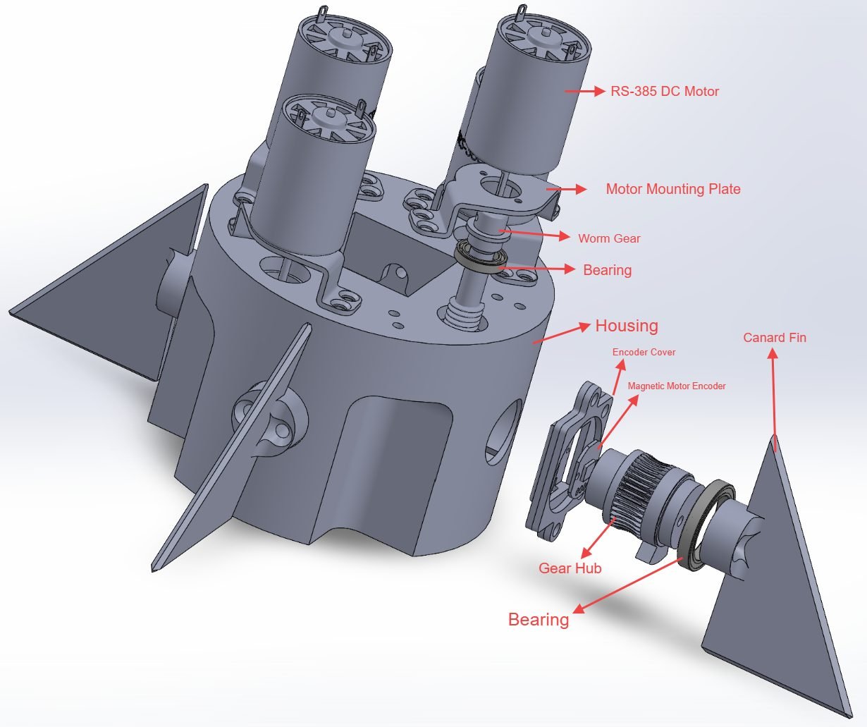
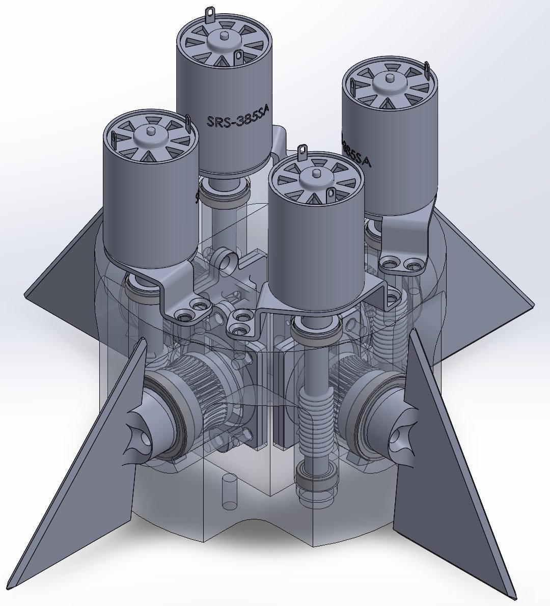
Design a 3D-printed testing prototype as UW Rocketry's first four-actuator canard control system, capable of full 3-axis flight control. Two orthogonal canard pairs, each fin independently driven, let the flight computer command pitch, yaw and roll from one surface set. Built as a 3D-printed prototype inside a 4-inch airframe, which set both the packaging envelope and the actuator budget.
Outcomes and contributions
- Led R&D and built the complete SolidWorks assembly for the team.
- Introduced the team's first worm gear drive, solving a torque shortfall no servo within budget could meet at this diameter.
- Passed design review with a complete BOM, schedule and manufacturing plan. Parts not yet printed or assembled.
Design decisions
- DC motor and worm gear instead of servos. An RS-385 through a 50:1 worm gives high reduction in a small envelope and turns the drive axis 90°, so motors sit axially along the tube while canard shafts run radially. That layout is what lets four actuators fit a 4-inch diameter.
- Assembly from outside in (DFM). Every part installs through the outer face of the housing, so the mechanism is serviceable without splitting the structure.
- Non-backdrivable drive. The worm cannot be driven in reverse, so aerodynamic hinge moment cannot force a canard off its commanded position.
- Backlash and friction trade. Tight worm-to-gear centre distance reduces backlash, since lost motion at the gear becomes deflection error at the fin, but too tight adds friction and steals torque.
- Worm on two bearings to hold mesh position under load, with a second bearing carrying the canard shaft at the fin end.
- Magnetic encoders per gear hub, feeding a four-driver board below the assembly for canard position tracking.
- Print process split by duty: resin for worm gears and gear hubs, where tooth definition drives mesh quality and backlash; PLA for housing and structural parts.
Technical details and skills
- Complete SolidWorks assembly to a 4-inch internal diameter constraint, with BOM, schedule and manufacturing plan.
- Worm drive design: 50:1 ratio, centre distance and backlash control, bearing support.
- Hinge moments at max-Q and maximum deflection from Ansys CFD, feeding static structural FEA on the housing, worm shaft and printed gear hub.
- Design for assembly and serviceability, actuator and sensor integration, additive manufacturing constraints.