Unlinked Canards Control System
- Where
- UW Rocketry
- When
- October 2025
Objective
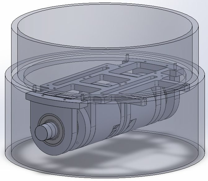
Design mechanical layout for a UW Rocketry independently actuated, unlinked canard control system, replacing a linked mechanism in which both canards were bound to a common shaft and could only deflect in unison. Independent actuation lets the flight computer mix commands: symmetric deflection for pitch or yaw, differential deflection for roll authority the linked design could not produce at all. The whole mechanism, two actuators, flight control board and batteries had to fit inside a 7.5-inch airframe tube.
Outcomes and contributions
- Sole designer of the system, delivered as a complete SolidWorks assembly with fully dimensioned parts.
- Predicted mass reduction of ~600 g against the previous linked system, with 50% more component volume freed inside the airframe. Currently pending manufacture.
- Freed volume goes to battery and wiring runs, recovery and payload subsystems, and a larger camera system than the airframe previously allowed.
Design decisions
- Removed the central pass-through. A linked pair needs a shaft or gearing spanning the fuselage diameter. Mounting an independent servo per canard near the outer wall clears the core of the tube, which is where the 50% volume saving comes from.
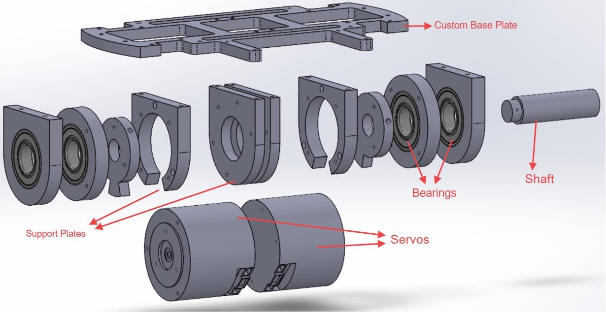
- Custom base plate carrying the flight control board, two 3S LiPo batteries and the canard mechanism beneath, packing the stack vertically within a fixed tube diameter.
- Front and rear support plates constraining each motor at both ends rather than cantilevering it off one face, holding alignment under launch loads and vibration.
- Added shaft bearings on the torque path to the canards. Sized to overcompensate for expected torque, since shaft wind-up costs control authority directly: commanded deflection stops matching actual deflection.
- Two CubeMars AK45-10 KV75 servos integrated with full mounting interfaces and fastener locations.
- Fully dimensioned every mounting hole for electronics, batteries, fasteners and actuators.
Technical details and skills
- Complete SolidWorks assembly and detail drawings, packaged to a 7.5-inch internal diameter constraint.
- Actuator integration, bearing and shaft support design, structural layout for launch and vibration loads.
- Design for assembly and serviceability, mass and volume optimisation.